


In the field of trenchless construction, Horizontal Directional Drilling (HDD) has become the go‑to technology for underground pipeline installation. The key device that ensures the drill bit accurately follows the designed trajectory is the HDD locator (also called a horizontal directional drilling steering tool). This article provides an in‑depth analysis of how an HDD locator works, helping you fully understand this “underground eye” and its operation.
What Is an HDD Locator?
An HDD locator is the core device used in horizontal directional drilling to track the drill bit in real time, monitor its attitude, and guide the drilling direction. It works like an underground navigation system, enabling operators to “see” the drill bit dozens of meters below the surface, ensuring that the borehole follows the preset path and avoids existing underground utilities and obstacles.
A complete HDD guidance system typically performs three major functions: Steering, Surveying, and Tracking.
Core Components of an HDD Locator
To understand how an HDD locator works, you must first know its three essential parts:
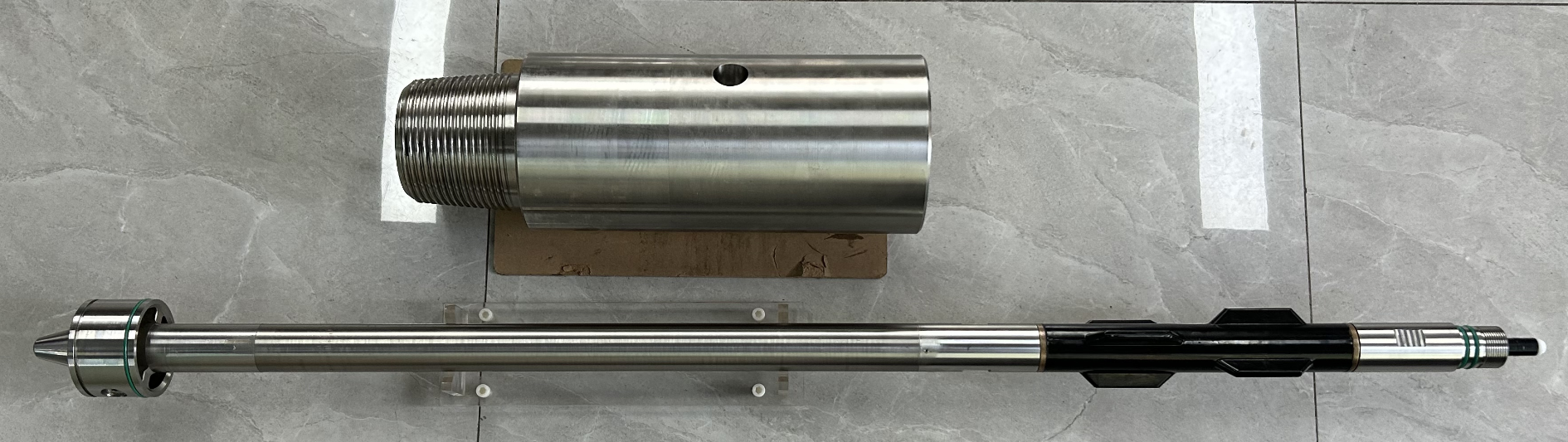
1. Transmitter (Sonde)
The transmitter is installed in a cavity behind the drill bit and serves as the “signal source” of the entire system. It houses precision sensors such as inclinometers, magnetometers, and accelerometers, which continuously measure critical parameters including the drill bit’s pitch angle (inclination), tool face angle (rotation around its own axis), azimuth angle (horizontal direction relative to magnetic north), and temperature. These data are transmitted to the surface via wireless electromagnetic waves through the transmitting coil.
2. Receiver
The receiver is a handheld locating device carried by the steering operator. It picks up the electromagnetic signals from the downhole transmitter, demodulates the transmitted parameter information, and simultaneously determines the drill bit’s horizontal position and depth based on the signal strength distribution.
3. Driller’s Display
Mounted on the drilling rig, this screen converts the data received from the receiver into intuitive graphical trajectory information, showing the drill bit’s underground position, depth, and heading in real time. The operator uses this information to identify deviations and adjust drilling parameters promptly.
How Does an HDD Locator Work? – Detailed Working Principles
The core principle of how an HDD locator works can be summarised as: downhole transmission → surface reception → data analysis → trajectory correction. Different types of locating systems achieve this in slightly different ways. Currently, the most common HDD locating systems fall into three main categories:
1. Walk‑Over Locating System
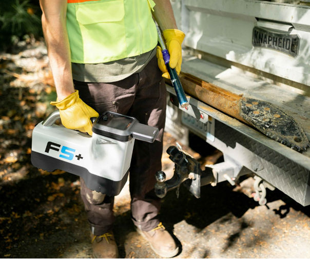
The walk‑over system is the most widely used HDD locating method today.
Working principle: The HDD sonde behind the drill bit emits a dipole magnetic field. The handheld receiver on the ground uses built‑in three‑axis orthogonal antennas to capture this magnetic field. The operator must manually move the receiver to the ground position directly above the drill bit and determine the horizontal position and depth based on the signal strength distribution.
Applications: Suitable for most conventional HDD projects. The system is relatively simple to set up and provides highly efficient and accurate information for shallow drilling.
Limitations: Performance can be compromised in deep drilling or environments with heavy interference (e.g., near water sources or dense utility networks).
2. Wire‑Line Locating System
The wire‑line locating system uses a wired cable to connect the downhole probe to the surface equipment, ensuring stable signal transmission.
Working principle: The probe transmits real‑time data (pitch, azimuth, tool face, etc.) to the surface via a cable inside the drill rods. The surface equipment decodes the signals and displays the drill bit’s position and trajectory on a computer. Some systems also use artificial magnetic fields arranged on the ground; the downhole probe detects these fields and sends data back via electromagnetic pulse wireless transmission.
Advantages: Stable and reliable signal, capable of precisely recording the drill bit’s 3D position (depth, left/right offset, and along‑hole distance) over longer ranges. Ideal for long‑distance, deep, and complex geological crossings.
Applications: When wireless signals are severely disrupted or when ultra‑long‑distance precision is required, the wire‑line system is the best choice.
3. Gyro Steering System
The Gyro Steering System is one of the most accurate HDD positioning methods available.
Working principle: It utilises the Earth’s gravity and magnetic fields for directional drilling. The downhole sensor package employs aerospace‑grade solid‑state inertial navigation technology to measure the drill tool’s pitch angle, magnetic azimuth, and tool face angle. Unlike electromagnetic systems, gyro‑based systems are immune to external electromagnetic interference, maintaining high accuracy even in heavily disturbed environments.
Applications: Particularly suitable for long‑distance drilling, dense urban areas, and sites with severe electromagnetic interference.
Cautions: These devices are more sophisticated and costly, and they may experience some drift that requires periodic calibration.
Magnetic Guidance System – A Specialised HDD Steering Tool
The magnetic guidance system is a type of HDD steering equipment widely used in recent years for long‑distance and large‑depth crossing projects.
Working principle: It determines the line orientation between two points using the Earth’s magnetic field, and the steering operator sends directional commands to the driller accordingly. The system typically consists of surface equipment (portable computer, interface panel, handheld receiver, driller’s display) and a downhole probe (magnetic guidance sonde with wireless transmitter). The probe gathers pitch, magnetic azimuth, and tool face data, sends them to the surface, and after decoding, the system displays the real‑time position and trajectory.
Key Factors Affecting HDD Locating Accuracy
In actual construction, the following factors can impact the accuracy of an HDD locator:
Electromagnetic interference – nearby power lines, metallic pipelines, traffic loop detectors, etc., can disturb electromagnetic signals.
Signal attenuation – wireless signals weaken as drilling depth increases.
Geological conditions – different strata (sand, clay, rock) affect signal propagation differently.
Equipment selection – different HDD locating systems have varying depth and accuracy capabilities; the right system must be chosen based on project requirements.
How to Choose the Right HDD Locating System?
When selecting an HDD locator, consider the following factors comprehensively:
Drilling depth and distance – use walk‑over systems for shallow, short runs; opt for wire‑line or gyro‑based systems for deep, long crossings.
On‑site interference – prioritise wire‑line or gyro‑based systems in areas with heavy electromagnetic disturbance.
Budget and accuracy requirements – gyro‑based systems offer the highest precision but come at a higher cost.
Ease of operation – walk‑over systems are simple to set up and user‑friendly, making them suitable for most routine projects.
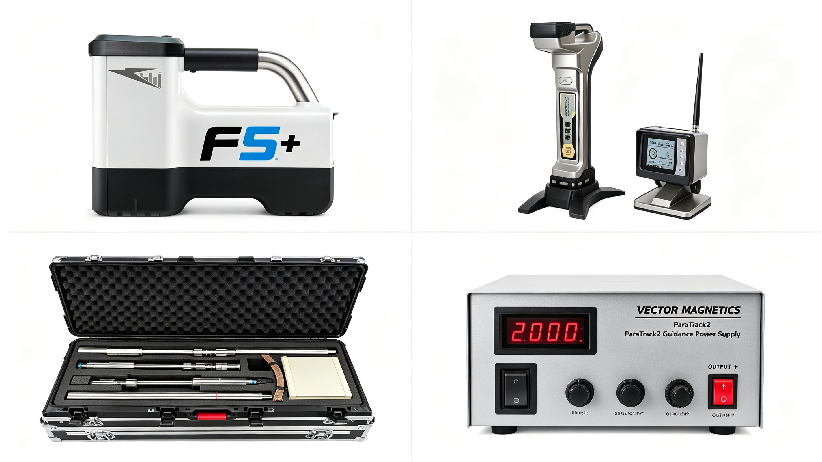
How an HDD locator works is essentially a coordinated downhole‑surface real‑time positioning and navigation process. Whether it is a walk‑over system, a wire‑line system, or a gyro‑based system, the core logic remains the same: the downhole transmitter collects drill bit attitude data, the surface receiver interprets positioning information, and the driller’s display presents the trajectory graphically – all working together to achieve precise steering control in horizontal directional drilling.
Understanding how an HDD locator works not only helps construction crews select and use the guidance instrument correctly – which is often the primary factor determining project success – but also significantly improves construction efficiency and safety, ensuring the smooth completion of underground pipeline installation projects.
As a global directional drilling equipment supplier, we provide all types of HDD equipment, if you have any questions, please contact HDD Master!