


In trenchless crossing projects, the HDD drill rod is the only force-transmission channel between the drilling rig and the drill bit—the rig’s axial thrust, rotary torque, and pullback force all rely on the drill rod to be transmitted to the bottom of the hole. Once the drill rod fails, the consequences can range from stopping drilling to replace the pipe, to a broken pipe downhole and crossing failure, with economic losses reaching hundreds of thousands or even millions. Based on engineering practice and integrating the core content of the international workshop Drill String Failure: Prevention and Remedial Action, this article systematically reviews the common causes of horizontal directional drilling drill rod failure and provides targeted solutions for construction management and technical personnel.
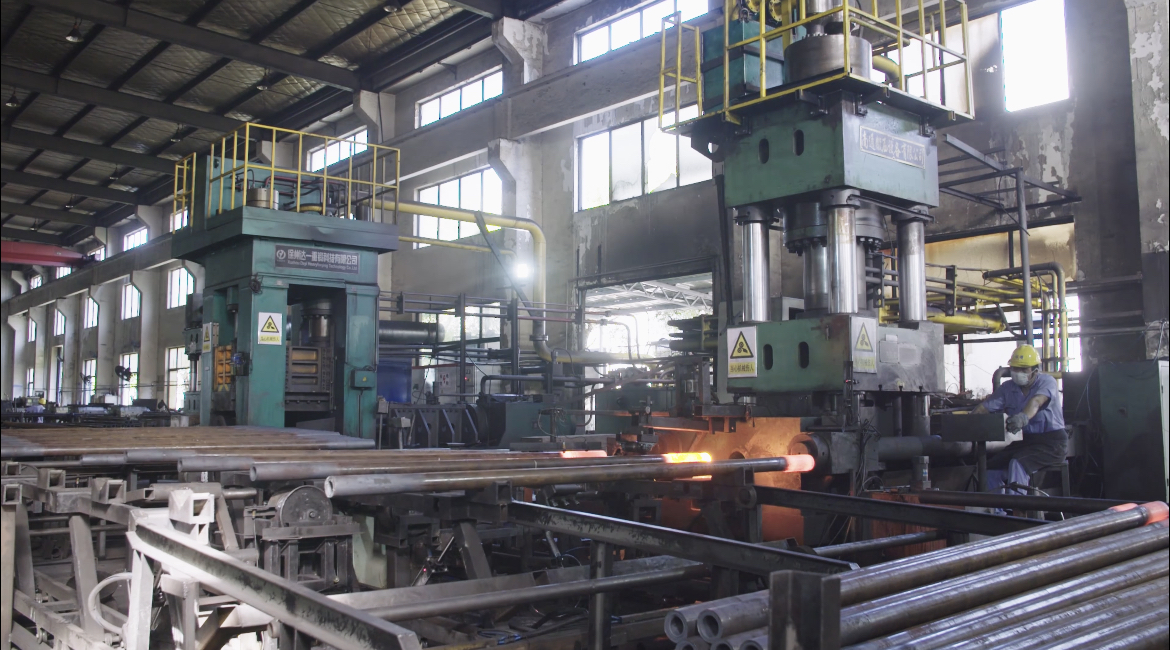
Common Causes of HDD Drill Rod Failure
Main Fracture Types: Torsion, Tension, Combined, and Fatigue
From the perspective of fracture mechanics, the main fracture conditions of HDD drill rod can be divided into four categories:
· Torsion failure: torque exceeds the load-bearing limit of the drill rodjoint or pipe body;
· Tension failure: axial tensile force is excessive during pullback or stuck-pipe conditions;
· Combined Torsion + Tension: drilling and pullback act simultaneously, causing loads to superimpose;
· Fatigue Failure: alternating loads accumulate over time, leading to crack initiation and propagation.
Among these, fatigue fracture is the number one killer in HDD drill rod failure and is also the most difficult type to detect and prevent.
Fatigue Fracture — The Number One Killer of Drill Rod Failure
The main failure modes of drill rod can be divided into two major categories: breakage and washout/piercing, both of which are closely related to fatigue and corrosion. Fatigue damage manifests as drill rod body fracture, permanent deformation of the pipe body, fracture at the transition section from the pipe body to the joint, and fracture at the threads of the male and female joints.
The Weihe River HDD crossing project of the Second West-East Gas Pipeline is a typical case. During the sixth-stage reaming, the drill rod fractured, causing the crossing to fail. Subsequent analysis of fracture morphology, chemical composition, and mechanical properties determined that it was fatigue fracture failure. Finite element analysis showed that the connection between the drill rod and the reamer is most significantly affected by alternating stress and is a high-incidence location for fatigue failure.
According to the summary of the international workshop, fatigue failure has the following characteristics:
· Difficult to detect and prevent;
· Stress level far below operating stress, so conventional strength checks are unlikely to find it;
· Fatigue damage accumulates continuously;
· Cyclic loading: rotation while buckled, rotation while bent, vibration, etc., all generate cyclic loads;
· Fatigue cracks grow progressively, eventually leading to sudden fracture.
What factors accelerate fatigue? Unreasonable reaming stages are an important driver. To meet schedules, some construction units reduce the number of reaming stages, causing drilling torque to increase substantially, drill rod wear to intensify, and fatigue life to shorten significantly. In addition, excessive pilot hole deviation greatly increases the bending moment borne by the drill rod during later correction, also accelerating the initiation and propagation of fatigue cracks.
Joint Thread Damage — Galling, Thread Swelling, and Heat Cracking
The drill rod joint is the “articulation” of the entire drill rod and also its weakest link. Common joint failure modes include galling, thread swelling, longitudinal thread cracking, and plastic deformation caused by friction and wear.
Galling is often related to poor thread surface treatment, thread corrosion, or failure to use proper thread compound. Under high-torque conditions, the thread metals come into direct contact and undergo cold-welding adhesion; when the joint is made up or broken out, the surface tears off, and the joint is scrapped.
Friction-induced heat cracking of joints is an easily overlooked problem. In curved borehole sections, the drill rod joint periodically contacts and rubs against the borehole wall. The surface is repeatedly heated and cooled, forming a brittle martensitic layer. Under bending moment, the internal thread undergoes longitudinal cracking. This type of damage is concealed and difficult to detect by routine visual inspection; it often leads to sudden fracture during the next drilling stage.
To address insufficient load-bearing capacity of joint threads, studies show that optimizing thread structural parameters can significantly improve performance. When the thread parameter combination is a taper of 1:16, a pitch of 6.25 mm, a thread height of 3.195 mm, a load flank angle of 28°, and a stab flank angle of 32°, the tensile performance of the drill rod joint can be increased by 9.8%, and the compressive performance by 15.2%. These data provide direct reference value for drill rod selection and joint repair.
Overload Fracture During the Pullback Stage
Pullback is the stage in HDD construction when the drill rod bears the greatest load. The Jiangsu Coastal Pipeline Rudong–Changshu–Taicang gas transmission pipeline project provides a typical case: the HDD crossing length was 1,818.43 m, and the pipe diameter was 1,016 mm. On October 30, 2022, main pipeline pullback began. At 14:30, when the 72nd drill rod entered the hole, the pull force suddenly increased from 150 t to 240 t, and the drill rod immediately fractured.
Analysis of the causes showed that excessive pullback starting force was the direct trigger. Because the access road at the construction site was restricted, a full-length launching trench could not be excavated. The prefabricated pipe section used roller stands plus earth-bag supports, which produced significantly higher frictional resistance than a full-length launching trench. At the same time, the pullback pipeline was laid along National Highway G328. Frequent heavy vehicle traffic disturbed the area above the borehole, worsening borehole wall stability and further increasing pullback frictional resistance.
The lesson from this case is clear: pullback force estimation cannot rely only on theoretical calculation. It must fully consider the superimposed effects of site conditions—launching method, surface traffic, and formation stability—on pullback resistance.
Improper Selection and Use Management
The root cause of many HDD drill rod fracture accidents is not the drill rod itself but improper selection and use management. Specific manifestations include: the drilling rig tonnage does not match project requirements; uneven drilling force and stop-and-go construction lead to poor borehole quality; the reamer is improperly selected and not matched to formation conditions, causing abnormally increased torque; and drill rods lack tracking management and inspection data statistics, resulting in large differences in wear among the same set of drill rods, with the weakest pipe failing first.
In addition, lack of drill rod grade management is also a common problem. Drill rods entering the site are not inspected and graded for use in accordance with the SY/T 5824 standard, and pipes with excessive wear are still put into high-load working conditions, directly creating hidden risks of fracture.
The ADIOS-Based Prevention System for HDD Drill Rod Failure
The international drill string failure prevention workshop proposed a concise and effective ADIOS prevention framework, which systematically controls drill rod failure risk from five dimensions: Attributes, Design, Inspection, Operation, and Surroundings. This framework also provides directly applicable guidance for HDD drill rod management.
Attributes: Control Intrinsic Drill Rod Quality from Dimensions, Metallurgy, and Manufacturing Process
Drill rod attributes include:
· Dimensions and shape: outside diameter (OD), inside diameter (ID);
· Metallurgical properties: specified minimum yield strength (SMYS), toughness, hardness;
· Manufacturing process: friction welding, integral forging, etc.
These attributes jointly determine the drill rod’s load capacity, flexibility, and durability. When selecting HDD drill rod, one should not look only at tonnage and price, but also at steel grade, wall thickness, joint type, welding process, and heat treatment quality. For long-distance, high-pullback-force projects, drill rods with good toughness and high fatigue life should be given priority.
Design: Drill String Assembly and Bottom Hole Assembly Configuration
The core tasks at the design stage are:
· Select components;
· Configure the bottom hole assembly (BHA).
Design objectives include:
· Accept the applied loads;
· Avoid stress excursions;
· Resist failure.
In HDD, this means that drill rods, reamers, drill collars, and heavy-wall drill rods should be reasonably configured according to crossing length, pipe diameter, formation conditions, and pullback force. Using several stands of heavy-wall drill rod at the reaming bit to increase stiffness can effectively reduce “whipping” near the reaming bit and lower the risk of drill rod fracture.
Inspection: Prevent Unexpected Fatigue Failure
Used drill string components have been subject to:
· Wear and tear;
· Handling damage;
· Unknown amount of fatigue damage.
The purpose of inspection is to prevent unexpected fatigue failure. Drill Rods entering the site should be inspected and graded in accordance with SY/T 5824, Drill rod Grade Inspection Method. For projects with high schedule risk, Grade I drill rods should be used. During long-term use, drill rods develop defects such as fatigue cracks, corrosion pits, and wall-thickness reduction. As defects worsen, drill rods gradually downgrade from Grade I to Grade II, and from Grade II to scrapping. Therefore, regular inspection and grading are the foundation for failure prevention.
Operation: Comply with API RP7G and Make-Up Specifications
The operation stage should strictly implement the following requirements:
· Observe API Recommended Practice RP7G;
· Make up tool joints to specification;
· Avoid dirt in threads;
· Always use thread protectors;
· Ensure alignment at pipe-side stabbing;
· Ensure pipe-side make-up;
· Train personnel.
These seemingly basic operational details are precisely the direct cause of many drill rod failure accidents. Failure to meet make-up torque requirements can lead to thread damage, bell-mouthing, and “mushroom head” defects, significantly shortening drill rod life. Therefore, standardized operating procedures must be established, and on-site personnel must receive continuous training.
Surroundings: Borehole Conditions, Straightness, Formation Changes, and Vibration
The environment of the drill string includes:
· Borehole conditions;
· Straightness: doglegs, offsets;
· Formation changes;
· Vibration.
In HDD, excessive pilot hole deviation, severe doglegs, alternating soft and hard formations, and severe drill string vibration will significantly increase the bending stress and fatigue damage of the drill rod. Therefore, strictly controlling the pilot hole trajectory, scientifically staging reaming, optimizing drilling fluid performance, and monitoring changes in torque and pull force are all important measures for improving the drill rod’s surrounding environment.
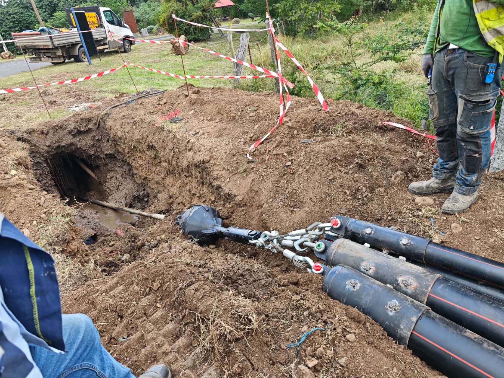
Systematic Solutions for HDD Drill Rod Failure
Optimize Drill Rod Selection and Drill String Assembly
Reasonably match rig capacity. Drill rods selection should match the drilling rig parameters, and the maximum torque borne by the drill rod should be selected at twice the maximum estimated torque. Before starting work, geological survey data should be carefully studied, and the construction plan and proposed equipment should be reviewed to ensure that the equipment matches the actual project requirements. Work should not begin if requirements are not met.
Use heavy-wall drill rod at key positions. In long-distance crossing projects, insufficient stiffness and buckling strength of conventional drill rod can cause “whipping,” making the pipe body prone to fatigue fracture. Using several stands of heavy-wall drill rod at the reaming bit to increase stiffness can effectively reduce whipping near the reaming bit and lower the risk of drill rod fracture. At the same time, 2–3 upset drill rods should be placed before and after the reamer to transition between the drill rod and drill collar.
Pay attention to differences in drill rod manufacturing processes. At present, HDD drill rods are mainly produced by two manufacturing routes: integral forging and friction welding. Integrally forged drill rods generally outperform friction-welded drill rods in fatigue life and joint strength, but they cost more. For high-risk, long-distance crossing projects, integrally forged drill rods offer better cost-effectiveness.
Establish a Full Life-Cycle Management System for Drill Rod
Grade-based inspection and use by grade. drill rods entering the site should be inspected and graded in accordance with SY/T 5824, drill rod Grade Inspection Method. For projects with high schedule risk, Grade I drill rods should be used. During long-term use, drill rods develop defects such as fatigue cracks, corrosion pits, and wall-thickness reduction. As defects worsen, drill rods gradually downgrade from Grade I to Grade II, and from Grade II to scrapping. Therefore, regular inspection and grading are the foundation for failure prevention.
Establish drill rod management records and implement rotation. Record the service condition of each drill rod throughout the process. Implement a rotation strategy during use: move pilot-hole drill rods to the rear of the drill string and place new drill rods at the front, so that wear is evenly distributed across the entire drill string and individual pipes do not fail first due to excessive wear.
Carry out finite element stress analysis and life assessment for high-risk projects. For HDD projects with high schedule risk, finite element simulation should be used to perform stress analysis and life evaluation of drill rods, predict the allowable number of stress cycles, and proactively replace them before reaching the critical value.
Strengthen Construction Process Control
Use scientific staged reaming; never attempt “one-step completion.” For pipelines with a diameter greater than 400 mm, reaming should be carried out in multiple stages. Generally, the first-stage reaming diameter is 20″–24″, followed by staged reaming with increments of 4″–10″. The reaming stage plan should be comprehensively determined based on rig capacity, drilling fluid system, and geological conditions, and must not be simplified to meet schedules.
Strictly control pilot hole deviation. The deviation between the actual pilot hole curve and the design curve should not exceed 1% of the crossing length. After pilot hole construction is completed, it must be accepted by the supervisor or owner, and only after passing acceptance can reaming begin. An excessively deviated pilot hole will impose additional bending moment loads on the drill rod during subsequent reaming and pullback.
Make adequate preparations before pullback. Before pullback, drilling fluid properties should be re-adjusted, and friction should be reduced by replacing with fresh fluid and lowering fluid density. For large pullback operations, auxiliary equipment such as pipe pushing machines should be prepared in advance; it should not be assumed based only on experience that “pullback can be completed without assistance.” Based on the lessons of the Jiangsu Coastal Pipeline project, a detailed analysis of the crossing formation and surface soil should also be conducted before pullback. In areas with complex surface traffic, coordination with traffic authorities should be carried out in advance to reduce disturbance to borehole stability during construction.
Strengthen process monitoring and hole cleaning. During reaming, changes in parameters such as torque and pull force should be closely tracked. If parameters are found to increase abnormally, hole cleaning should be carried out promptly, and reaming should continue only after cleaning is completed. For HDD in fractured rock formations, hole cleaning should be performed at least once after each reaming stage to prevent cuttings accumulation from causing drill tool sticking.
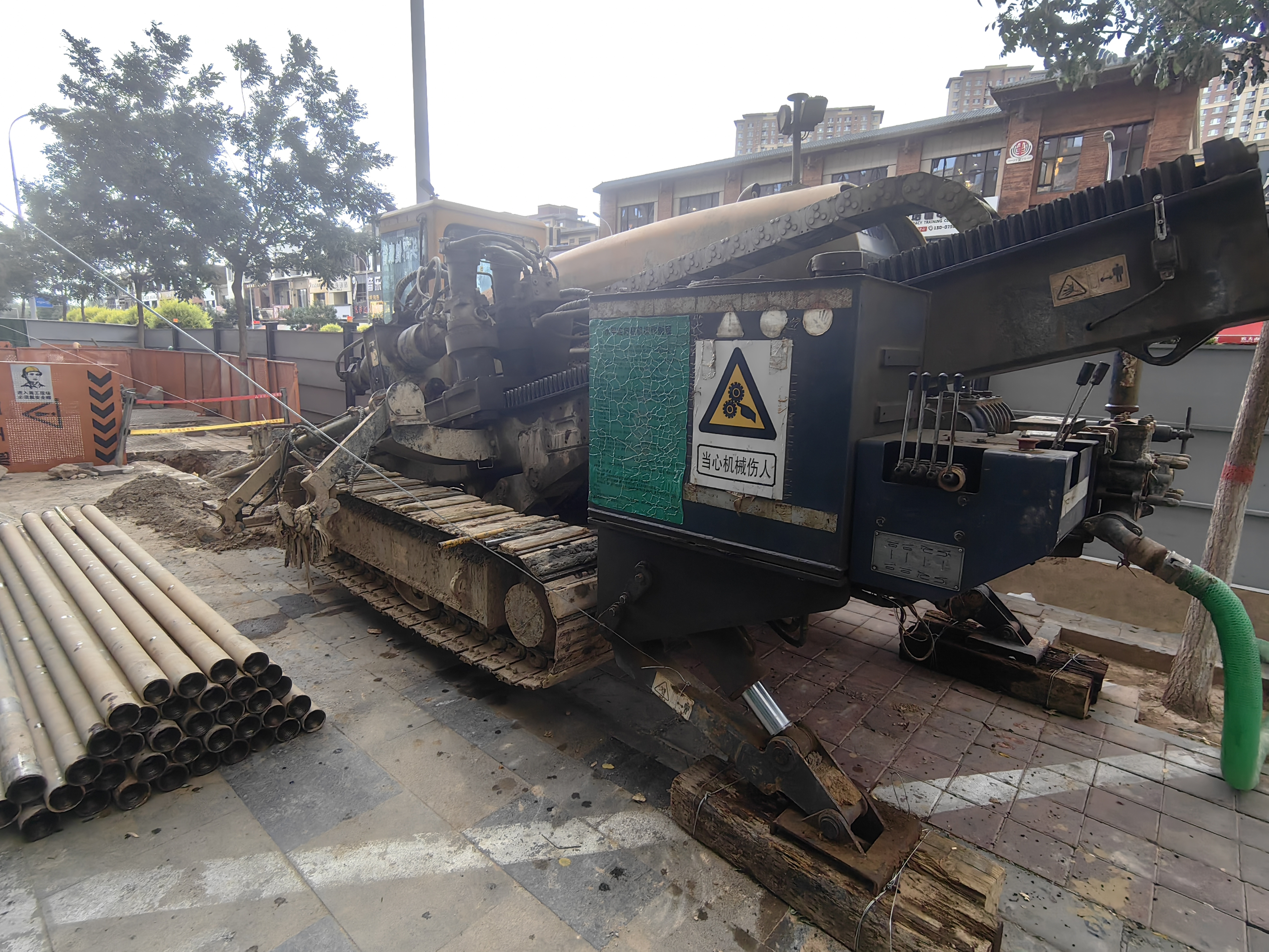
Remedial Action: Emergency Response After Drill Rod Failure
Although prevention is central, once drill rod fracture or failure occurs, remedial action must be taken quickly. This generally includes:
· Accurately determine the breakpoint location: comprehensively judge through drill rodcounting, fishing marks, and downhole inspection;
· Fishing operations: use fishing spears, fishing overshots, washover pipes, and other tools for recovery;
· Jarring to free stuck pipe: if the drill rodis stuck or buried, jars or surface jarring may be required to free it;
· Clean up downhole fish: prevent impact on subsequent reaming and pullback;
· Evaluate the remaining drill string: urgently inspect the same batch of drill rods to avoid secondary fracture;
· Adjust the construction plan: analyze the cause of failure, optimize the drill string assembly, reaming stages, and pullback parameters before resuming construction.
The goal of remedial action is not only to fish out the broken pipe but also to prevent the same type of failure from recurring on the same project.
The key to preventing HDD drill rod failure lies in establishing a full-chain management system covering “selection—design—inspection—operation—environment.” Integrating the ADIOS prevention framework—from drill rod attributes, drill string design, graded inspection, and API RP7G operating specifications to borehole environment control—an oversight in any link can become the fuse for a pipe break accident. For construction companies, valuing refined drill rod management is not only about being responsible for a single project but also a long-term investment in equipment assets and personnel safety.