


A technical deep-dive into pullback force calculations, drilling fluid dynamics, and rig selection for successful horizontal directional drilling operations.
Watching a horizontal directional drilling (HDD) rig pull hundreds of tons of pipeline underground seems almost impossible—yet it happens every day beneath rivers, highways, and environmentally sensitive areas. For contractors, engineers, and project managers, understanding the mechanics behind that pullback force is essential for rig selection, risk management, and successful project execution. In this guide, we break down exactly how HDD rigs generate and manage the massive force required to install pipelines without open trenches.
What Determines Pullback Force? The Key Factors
Before we dive into how rigs generate massive pulling power, let’s understand what they’re pulling against. The total resistance a rig must overcome during pullback comes from several sources.
Key Factors Affecting Pullback Force
Several force components combine to create the total resistance the rig must overcome:
- Pipe-soil friction: The dragging resistance between the pipe surface and the surrounding formation. This factor tends to be high in unstable soils.
- Fluidic drag: Resistance generated by the viscous drilling fluid as the pipe moves through it. This is significant in all conditions.
- Pipe weight component: Side-wall pressure created by the pipe’s own weight, especially in curved sections. Its impact increases with larger pipe diameters.
- Bending resistance: The stress induced as the pipe conforms to the curved borepath. This becomes critical in tight radius designs.
According to research published in the Journal of Pipeline Systems Engineering and Practice, accurate pullback force estimation is necessary during the design stage to select both the appropriate product pipe and rig size . The product pipe must have adequate strength to avoid damage during installation, while the HDD rig must have sufficient capacity to successfully pull the pipeline.
The PRCI Calculation Method
The Pipeline Research International (PRCI) method has been widely adopted in the industry for pullback force estimation. This approach calculates total pull force by summing forces resisting pipe movement in both straight and curved segments of the borehole . The calculation accounts for:
- Borehole geometry and path curvature
- Soil properties along the bore path
- Drilling fluid density and rheology
- Pipe material properties and diameter
How the Force Is Generated
The rig’s pullback force comes from powerful hydraulic systems. A diesel prime mover drives hydraulic pumps that send high-pressure fluid to motors and cylinders. These components convert fluid pressure into linear pulling force through the rig’s carriage system, which grips and pulls the drill string section by section.
Real-world insight: Research comparing theoretical vs. measured pullback forces across 54 projects revealed something surprising. For small HDD rigs, actual forces were 35% higher than theoretical calculations. But for large HDD rigs, theoretical forces actually exceeded actual loads by 54% . Why? Better borehole conditioning, multiple reaming passes, and slower pull rates in large projects reduce the mechanical work required.
The Hole: Preparation Makes Pullback Possible
The Hole: Preparation Makes Pullback Possible
After drilling a small-diameter pilot hole along the precise design path, operators progressively enlarge the hole using reamers. The final hole diameter is typically 1.5 times larger than the pipeline itself. For a 20-inch pipeline, crews will ream through multiple passes: 6″ → 10″ → 14″ → 18″ → 24″ → 30″.
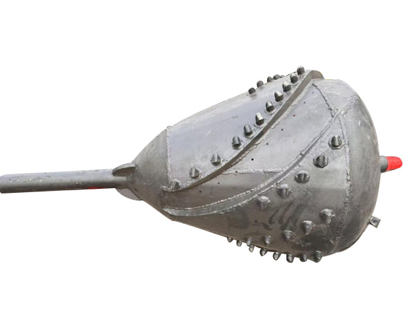
This oversizing creates:
- Annular space around the pipe (typically 4-6 inches of clearance)
- Reduced contact area between pipe and formation
- Path for drilling fluid to lubricate the pullback
The Fluid: Drilling Mud as Critical Lubricant
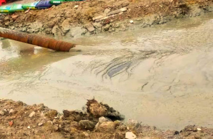
If the rig provides the muscle, drilling fluid (mud) provides the lubricant—and it’s far more sophisticated than simple water.
Why Mud Matters
According to Vermeer product manager Tod Michael, “Using drilling fluid with the right additive can help limit the risk of the hole collapsing” . Drilling fluid serves multiple critical functions during pullback :
Lubrication: The mud creates a slick, low-friction environment. As the pipe enters the hole, it essentially floats on a layer of lubricating fluid, dramatically reducing the coefficient of friction.
Buoyancy: With specific gravity typically ranging from 9 to 11 ppg (1.08 to 1.32 SG), the mud provides buoyant support. This reduces the effective weight of the pipe during pulling—imagine dragging a log across land versus floating it through water.
Hole Stability: The mud forms a thin filter cake on the borehole wall, preventing collapse and maintaining the open path for the pipeline.
Cuttings Removal: Proper fluid viscosity transports drill cuttings out of the hole, preventing them from accumulating and blocking the path.
Mud Properties That Affect Pullback
A parametric study of HDD pullback forces identified several fluid-related parameters that significantly impact pull loads:
Drilling mud density: Typically ranges from 9 to 14 ppg. Higher density increases buoyancy (reducing effective pipe weight) but may also increase fluidic drag.
Fluidic drag coefficient: Varies between 0.0025 and 0.0475 psi. This coefficient has a significant effect on pullback force in both small and large rigs.
Soil coefficient of friction: Usually between 0.2 and 0.4. Higher values increase resistance, particularly in smaller projects.
The research showed that changes in the fluidic drag coefficient resulted in the highest amount of variation in pullback force—making mud selection and properties absolutely critical to successful pulls .
Calculating Fluid Requirements
Knowing your hole volume is essential for proper fluid management. A simple formula helps estimate requirements:
Hole diameter² ÷ 24.5 = volume in gallons per foot
For an 8-inch back ream:
(8 × 8) ÷ 24.5 = 2.61 gallons per foot
Soil type determines the multiplier:
- Sand conditions: 2-3 × hole volume (requires fluid designed to minimize loss)
- Clay conditions: 3-5 × hole volume (requires additives to reduce swelling)
For a 200-foot bore in sand with an 8-inch ream: 2.61 gal/ft × 2 × 200 ft = 1,044 gallons of fluid required.
The Hardware: Specialized Components for Pullback
Beyond the rig itself, several specialized components make large-tonnage pullback possible:
Pull Heads and Swivels
The pipeline’s leading end is fitted with a reinforced pulling head, welded directly to the pipe. This component distributes tremendous pulling force across the pipe’s circumference rather than concentrating it at a single point.
Swivels connect the drill string to the pipeline and serve a critical function—they allow rotation of the drill pipe without twisting the pipeline itself. A stuck swivel would either snap the pipe or prevent rotation entirely.
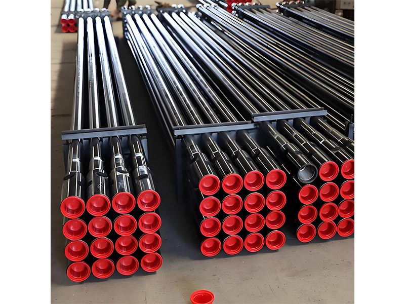
Thick-Wall Drill Pipe
For extreme pulls, operators use heavy-duty drill pipe with walls significantly thicker than standard pipe to transmit massive forces without buckling or breaking.
Fast Pullback Systems
Some manufacturers offer specialized pullback attachments that allow crews to pull product without removing the drill head.
Pullback Speed: The Critical Variable
One of the most common mistakes in HDD operations is pulling back too fast. According to drilling fluid expert Todd Tannehill, “Outrunning your drilling fluids has several potential consequences, including inadvertent returns, collapsed bores or stretched pipe”.
Calculating Optimal Pullback Time
Using the volume calculations above, you can estimate proper pullback time. For our 8-inch ream example requiring 52.2 gallons per 10-foot rod:
- At 20 gpm: 2.5-3 minutes per rod
- At 30 gpm: 1.5-2 minutes per rod
- At 30 gpm: 1.5-2 minutes per rod
The calculation is simple: 52.2 gallons ÷ 30 gpm = 1.7 minutes per rod.
Key insight: Higher viscosity fluids reduce pumping rate, so factor this into your time estimates.
Real-World Data: What the Numbers Tell Us
A comprehensive study of 54 HDD projects provides valuable benchmarks for the industry :
Project types:
- Pipe diameters: 114 mm (NPS 4) to 1,067 mm (NPS 42)
- Geological materials: Clay, silt, sand, gravel, clay shale, sandstone, siltstone, coal bedrock
- Geographical area: Alberta and Northern British Columbia
Key findings:
- In most cases, maximum rig force was recorded near pullback completion
- Better workmanship, equipment, and execution in large projects resulted in actual forces being 54% lower than theoretical maximums
- Poor borehole cleaning in small projects led to additional forces required to displace cuttings
The study concluded that “Proper conditioning of the borehole, multiple reaming passes and slow pull rate in large HDD operations eliminate excessive mechanical work required for pulling the pipeline”.
Practical Recommendations for Contractors
Based on industry research and field experience, here are actionable recommendations for successful pullback operations:
1. Match Rig Size to Project Reality
Don’t simply rely on theoretical calculations. Consider that small projects may see actual forces 35% higher than estimates, while large projects may need less capacity than calculated.
2. Invest in Borehole Conditioning
Multiple reaming passes and proper hole cleaning dramatically reduce pullback forces. The data shows this investment pays off in reduced rig stress and lower risk.
3. Get the Mud Right
Soil-specific fluid design is non-negotiable. In sand, focus on fluid loss control. In clay, address swelling and bit balling . Document your fluid program and adjust based on real-time observations.
4. Control Pullback Speed
Calculate your required fluid volume per rod and match your pullback speed to your pumping capacity. Rushing this step is one of the most common—and preventable—causes of bore failure.
5. Monitor and Document
Record actual pullback forces throughout the operation. These data points are invaluable for future project planning and estimating accuracy.
HDD pullback success comes down to engineering, not magic. It requires the right combination of hydraulic power, hole preparation, fluid chemistry, and operator experience.
Understanding what drives pullback force helps you make better equipment decisions and complete more successful installations. Whether you’re planning a major river crossing or a standard pipeline project, these fundamentals apply every time.
Frequently Asked Questions
Q: How is pullback force calculated for HDD rigs?
A: The PRCI method is widely used, summing forces from pipe-soil friction, fluidic drag, pipe weight components, and bending resistance along straight and curved bore segments.
Q: What’s the largest HDD rig pullback capacity available?
A: Large HDD rigs can require rigs with pullback capacities from 330,000 up to 1,100,000 lbs, with some modern rigs approaching 1,500 tons.
Q: Why does pullback speed matter?
A: Pulling too fast can outrun your drilling fluid, leading to hole collapse, stuck pipe, or stretched product. Proper speed ensures the hole stays full of fluid for stability and lubrication.
Q: How much drilling fluid is needed for pullback?
A: Calculate hole volume (diameter² ÷ 24.5 = gallons per foot), then multiply based on soil type: 2-3× for sand, 3-5× for clay. This ensures adequate lubrication and cuttings removal.
Q: What causes pullback force to vary between projects?
A: Key variables include soil conditions, borehole geometry, drilling fluid properties, pipe characteristics, and most importantly—quality of execution including borehole conditioning and pull speed.
Ready to optimize your next HDD project? Every job site is different, and the right equipment configuration makes all the difference. We provide customized solutions tailored to your actual operating conditions—helping you select the ideal engine, mud pump, drill pipe, and support components for maximum efficiency and reliability. Get a free job site evaluation and a personalized configuration proposal by contacting our engineering team today.